Showing posts with label Design. Show all posts
Showing posts with label Design. Show all posts
Sunday, 2 May 2010
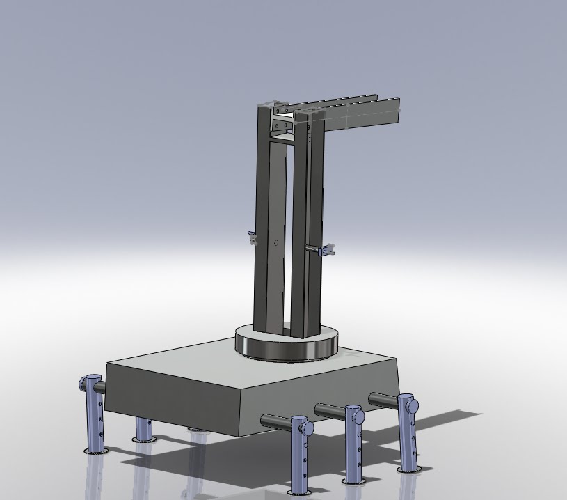
Our final Crane model
After a long period of designing and re-designing we finally finished with out crane model. below is a picture of of the final module.


Wednesday, 21 April 2010
The Pulley
Pulleys are a better way to lift large masses onto tall heights and are examples of simple machines.
The types of pulleys that had been researched included:
- Fixed pulleys:
- Movable Pulleys
- Compound Pulleys
- Block and tackle
For the project we decided to use the the fixed pulley system. This is a fixed or class 1 pulley with a fixed axle. That is, the axle is "fixed" or anchored in place. A fixed pulley is used to change the direction of the force on a rope (called a belt). A fixed pulley has a mechanical advantage of 1. A mechanical advantage of one means that the force is equal on both sides of the pulley and there is no multiplication of force

NOTE that
The number of pulleys used in a system may increase or decrease the mechanical advantage of the system. Generally, the higher the mechanical advantage is, the easier it is to lift the object.
This means no matter how easy it is to use the pulley system, the system itself is not very efficient due to the force of friction. For example, one has to pull two meters of rope of cable through the pulleys in order to lift an object one meter.
The types of pulleys that had been researched included:
- Fixed pulleys:
- Movable Pulleys
- Compound Pulleys
- Block and tackle
For the project we decided to use the the fixed pulley system. This is a fixed or class 1 pulley with a fixed axle. That is, the axle is "fixed" or anchored in place. A fixed pulley is used to change the direction of the force on a rope (called a belt). A fixed pulley has a mechanical advantage of 1. A mechanical advantage of one means that the force is equal on both sides of the pulley and there is no multiplication of force

NOTE that
The number of pulleys used in a system may increase or decrease the mechanical advantage of the system. Generally, the higher the mechanical advantage is, the easier it is to lift the object.
This means no matter how easy it is to use the pulley system, the system itself is not very efficient due to the force of friction. For example, one has to pull two meters of rope of cable through the pulleys in order to lift an object one meter.
Tuesday, 20 April 2010
Design assembly ( preliminary stage)

This is the first stage of the assembly of the our final design. The beams are mounted onto the rotating base. This base will contain ball bearings which whill allow the posibility for easy rotation when needed.
Outtriggers for Support

These are the structures that offer support to the crane structure on rough ground.
the holes help in changing levels to match an appropriate height.
Monday, 19 April 2010
The winch system to implement.
For the project we will be using two winches to operate the crane. The purpose of the first will be to lift the object to be moved from the ground to a suitable height above the ground. The second winch will be aimed at lifting the top H-beam to provide more height during lifting to avoid any obstacles.
Research into the different types of winches was made and it was noted thst there were three main parts to a winch. They are the spool and other parts related to holding the rope, strap or cable; the crank, power source, and gears; and the ratchet. These parts can be mixed relatively independently though some combinations are better than others.
So after careful analysis we decided use the Fulton 3,200lb Two Speed Cable Winch w/ Hand Brake - HP Series. This winch would be used for lifting the H-beam. its features include:
Product Length: 12.0 inches
Product Width: 9.0 inches
Product Height: 8.0 inches
Product Weight: 18.3 pounds
Package Length: 12.0 inches
Package Width: 9.0 inches
Package Height: 8.0 inches
Package Weight: 17.3 pounds
Description
3,200 lbs. Single Speed Capacity: 3,200 lbs. Gear Ratio: 5.1:1 and 12.2:1 Handle Length: 10

The second winch which we found was the T12 hand winch/manual winch. This is a winch which was designed to be used with cranes. product descriptions include:
Aplication: Cranes
Capacity: 1200kg
Power Source: Hand
Surface: Zinc

Research into the different types of winches was made and it was noted thst there were three main parts to a winch. They are the spool and other parts related to holding the rope, strap or cable; the crank, power source, and gears; and the ratchet. These parts can be mixed relatively independently though some combinations are better than others.
So after careful analysis we decided use the Fulton 3,200lb Two Speed Cable Winch w/ Hand Brake - HP Series. This winch would be used for lifting the H-beam. its features include:
Product Length: 12.0 inches
Product Width: 9.0 inches
Product Height: 8.0 inches
Product Weight: 18.3 pounds
Package Length: 12.0 inches
Package Width: 9.0 inches
Package Height: 8.0 inches
Package Weight: 17.3 pounds
Description
3,200 lbs. Single Speed Capacity: 3,200 lbs. Gear Ratio: 5.1:1 and 12.2:1 Handle Length: 10

The second winch which we found was the T12 hand winch/manual winch. This is a winch which was designed to be used with cranes. product descriptions include:
Aplication: Cranes
Capacity: 1200kg
Power Source: Hand
Surface: Zinc

Saturday, 17 April 2010
Metal Bars for support
.bmp)
These are placed at the top of the main beam structure to hold the main beam and rotating beams together.
Beam used in Lifting ( top)

This is the rotating beam situated at the top. With the help of the supporting bar, the winge system at the back and the eye bolt, the beam can move up and down to meet target objects before lifting and after lifting.
Note that in the final assembly, it is used as an H-beam. this was to ensure that the beam could be properly mounted onto the main crane supporting structure.
The main Beam structure.

This is the main structure which controls the weight og the object being lifted. Two winge systems will be install ; one at the back of the beam and the other to the side. The winge sytem to the back of the beam will help the top beam to be hoisted up and down such that it reached its target object before carrying out any lifting action. The winge sytem to the side will will be use to alternate the cord lengths.
To the side are aslo metal bars. these are positioned such that they can aid in the rotation of the whole crane system and eventually move object from one position to the another.
Friday, 16 April 2010

Thursday, 15 April 2010
Rotating base

This is another part of the base. It sits in the hole on the base to help ease the rotation. this part will be connected to another support to provide more stability. the rectangle intrusion at the top will be for mounting the top half of the crane i.e the beams and its upporting structure.
Finall Design in CAD Format

This is the base of the crane. There are holes on each side of the base and these are holes where the outriggers will be connected to help keep some stability to the system. There are six otf there. At the top, the intrusion provides room for the crane to rotate so the heavy load can be moved from one position to the other.
Monday, 5 April 2010
Factors
Factors affecting the crane development
•It cannot be too heavy as it would be too hard to move around.
• The whole assembly would need to be assembled and disassembled without specialist knowledge. It must be do able on the site.
• The cost of each component must also be taken into account as we cannot use very expensive material but at the same time do not compromise the quality.
• Each component was designed with the forces that will be acting on it in mind. The materials we have used are robust enough to hold the load.
• After maintenance - We used alloy metals for the beams because they are easily replaced without any special work. The beams would be under the most stress so therefore we made these replaceable. We have chosen steel as this is a very strong material and less likely to suffer damage in long term.
•It cannot be too heavy as it would be too hard to move around.
• The whole assembly would need to be assembled and disassembled without specialist knowledge. It must be do able on the site.
• The cost of each component must also be taken into account as we cannot use very expensive material but at the same time do not compromise the quality.
• Each component was designed with the forces that will be acting on it in mind. The materials we have used are robust enough to hold the load.
• After maintenance - We used alloy metals for the beams because they are easily replaced without any special work. The beams would be under the most stress so therefore we made these replaceable. We have chosen steel as this is a very strong material and less likely to suffer damage in long term.
Friday, 2 April 2010
Final Concept Sketchs

Looking at picture 1.
this was the rough sketch of the final design stipulating what sort of components to use and where to use them.

Picture 2
shows the side of the concept crane design ( upper half). this bit conatains, an eye bolt to help support the steel cords which will be used for pulling heavy objects.
Also below are sketches of the side views for the top beam indicating how the the cord will be passing through.

Picture 3
this indicates the meta bars that will be used when the crane is in operation, to help move the crane around after objects have been lifted.
The base of the crane also shown without the outriggers.
Note:
Sketches produced by the Arnold ( Chief Designer)
Monday, 22 March 2010


Wednesday, 17 March 2010
Initial Designs


Crane Design
Conditions we are considering:
1. To be able to be carried manually
2. Fit the crane in back of a 4 x 4
3. Ability to be assembled
4. Can be hand powered or motor powered
As decided in our last meeting, I designed my initial ideas for a crane that follows the conditions.
There is a potential problem that could occur if these designs were placed straight into the disaster areas. I am currently working on ideas on how to secure the base of the crane i.e. with wheels or fixed. In all situations they are designed to work on level ground. This will need to be considered in the design. Also the balance of the crane needs to considered as it will be used in disaster conditions.
We will update more after our next meeting on our detailed designs....
Friday, 12 March 2010

Wednesday, 10 March 2010

Subscribe to:
Posts (Atom)